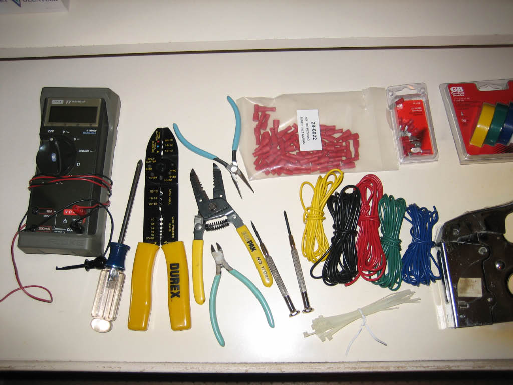
| For the control wiring, I decided to use 18 gauge braded wire.
20 or 22 gauge would have probably been easier to work with, but our local hardware store
only carried 16 and 18 gauge wire in multiple colors. I used approximately 30 feet of black and
approximately 25 feet each of red, green, blue, and yellow. For my next MAME project,
I'll buy the wire in bulk. All the connections were
made using .187 crimp-on quick disconnects. I used around 140 total.
|
| Here's most of the tools and stuff I used to wire the panel.
|

|
| I started by wiring up all the LEDs to the LED controllers. Each
RGB LED has a small ribbon cable with four leads - red, green, blue, and ground. I wired all the
blue leads to the first 32 port LED-Wiz and the red and green leads to the second LED-Wiz. This left
16 available ports on the first controller, of which I used an additional 4 for the volcano buttons.
The remaining 12 ports will eventually be used to light the track ball and joystick handles.
|
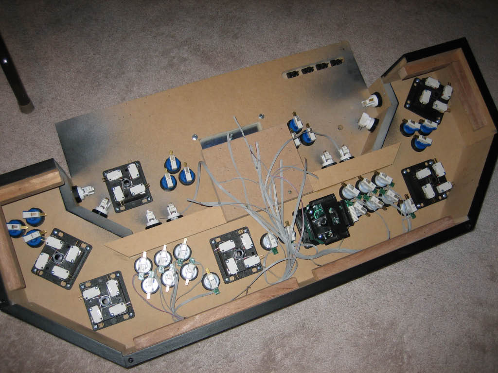
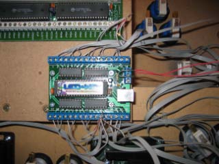
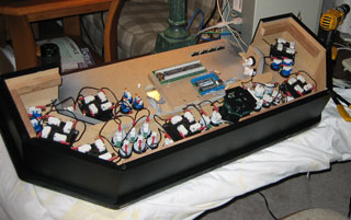
| The picture on the left shows the ribbon cables from all the Electric ICE buttons.
None of the controller boards have been mounted yet. The picture on the right shows the first of the two
LED controllers mounted and wired (incorrectly). After all the ribbon cables were wired, I neatened them
up with tie-wraps.
|
|
| Next I wired the common return for all the cherry switches. I cut black wire into
5 inch lengths and chained it all together with the quick disconnects. A few of the lengths between the switches
required slightly longer than 5 inches.
|
|
| Before wiring all the buttons and joysticks to the I-PAC interface, I loaded
up the Ultimarc I-PAC software (WinIPAC) and mapped all my switches to ports on the I-PAC. For reference,
I printed out the layout and taped it to the bottom of the control panel.
|


|
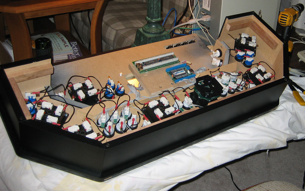
The I-PAC has 14 ports for each player. I decided to use a different color
wire for each set of player ports.
Tip: When wiring the joysticks, remember that the switches are opposite to
the joystick direction - for example, pushing left on the joystick clicks the switch on the right (when viewed
from the bottom).
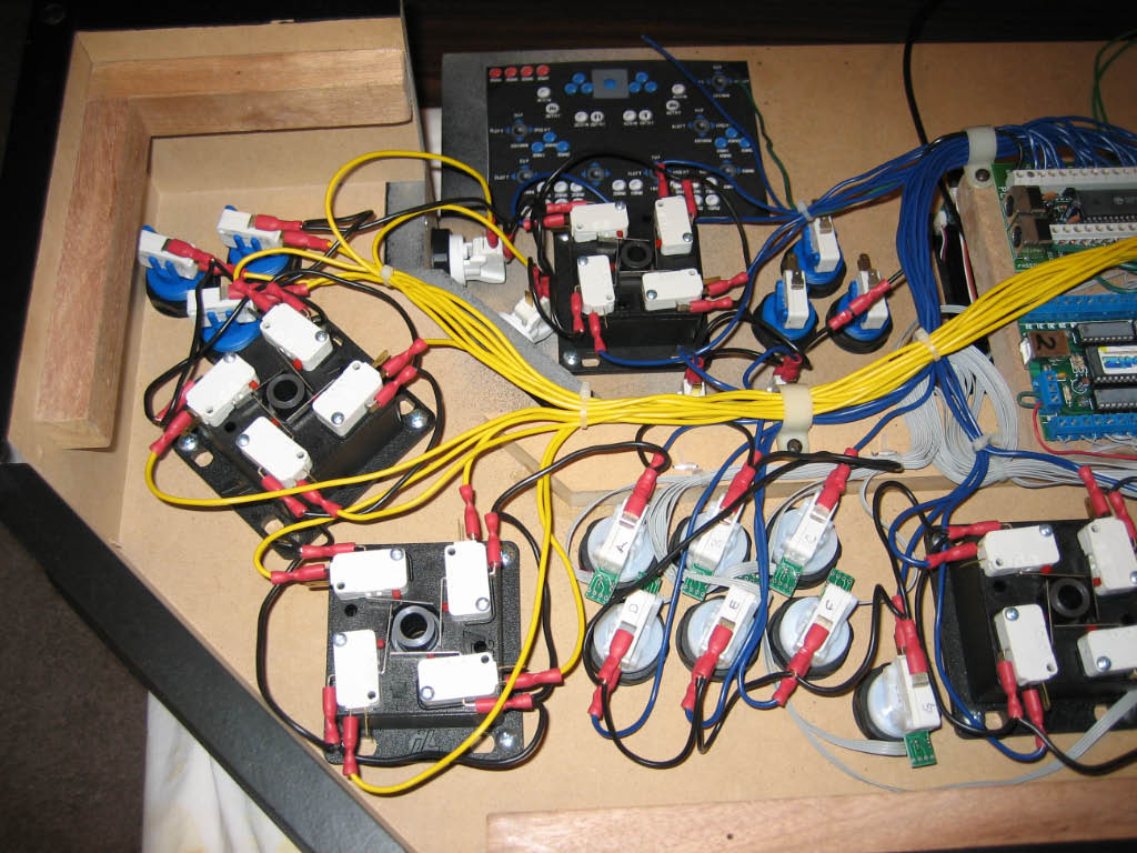
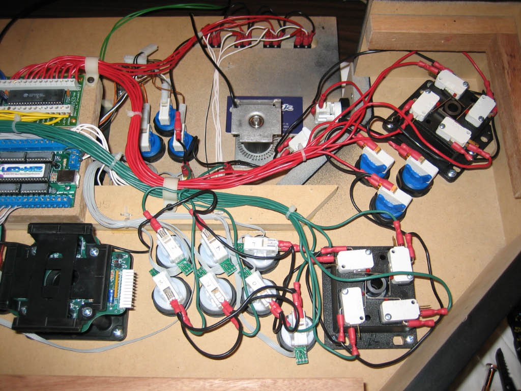
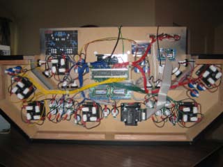
Here's two pictures of the completed wiring to all the switches.
|


|
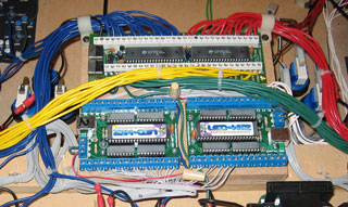
| Here a close-up of the completed wiring to the I-PAC and LED-Wiz's. For the LED ribbon
cables, I decided to coil the wire rather than cut it to length. This way, I can reuse the Electric ICE RGB Drives
in a new panel if I ever decide to rebuild in the future (not likely).
|
|
| Here's a picture of the track ball mounted and wired above the other circuit boards. Also
a picture of the wiring to the volcano switches and the GP-Wiz49. For the volcano LEDs, I soldered a 220 OHM
resisters to the end of each wire and crimped a quick disconnect to the other side of the resistor, then wrapped
it all in red electrical tape.
|


|
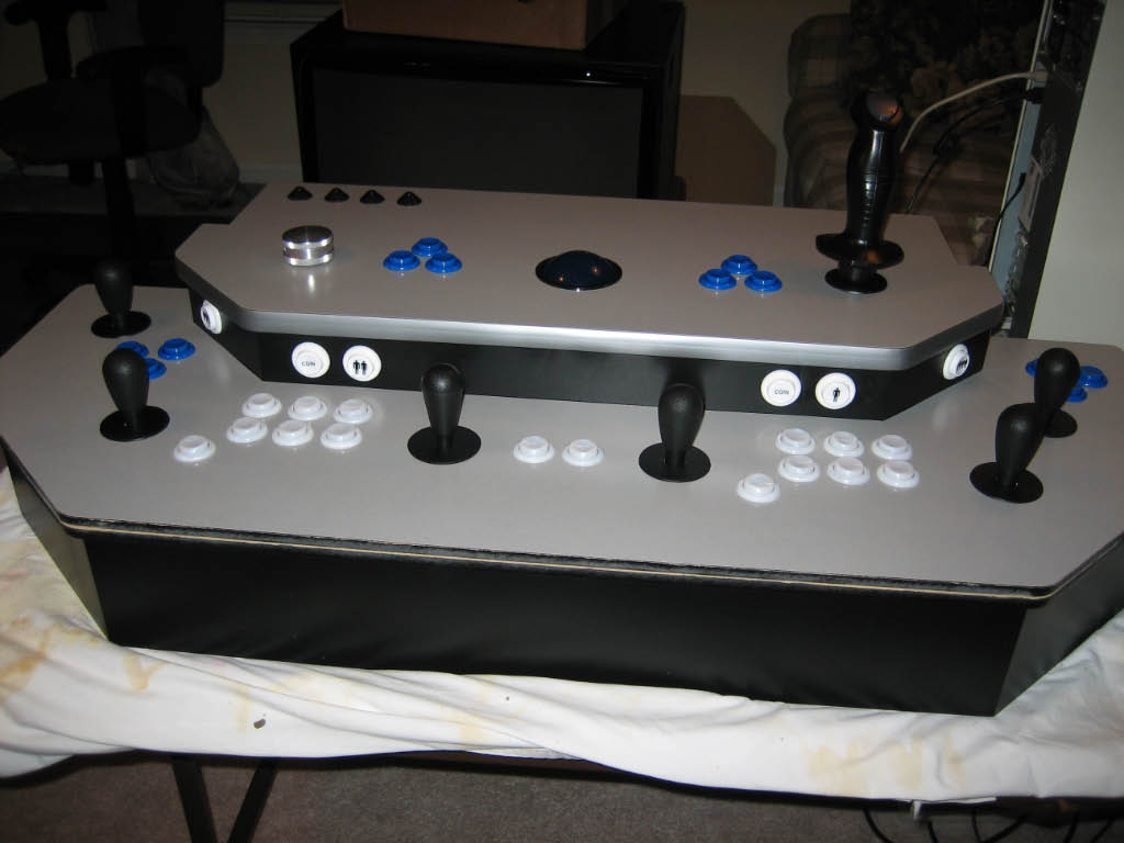
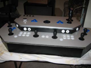
| So that's it. The control panel is complete!
|
|