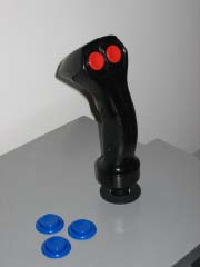
| Rather than spend $100 for a Happ 8-Way Trigger, I decided to follow the likes of
1Up and
Retropolis and build my own 8-way trigger from
an old PC analog stick (Raider Pro) and a Happ Super. A big thanks goes out to 1Up and Retropolis! Without
their information, I would not have tried this on my own.
|
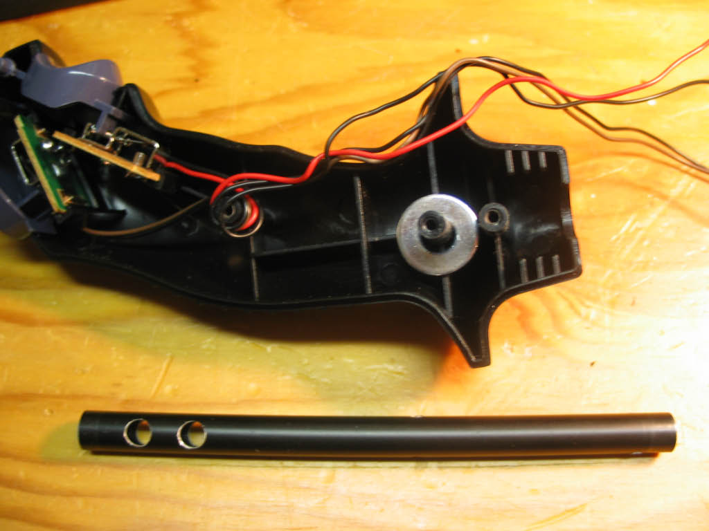
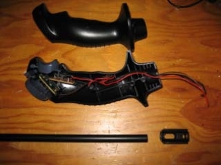
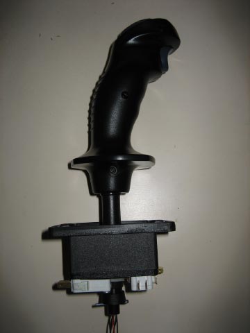
| First, the parts; I purchased a Happ Super for $5.99 on sale from HappControls (plus $7.11 for shipping and tax).
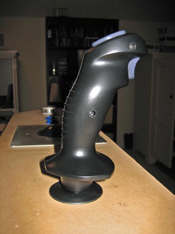
For the joystick handle, I used the Raider Pro as recommended by Retropolis. It's a well made stick
with a trigger up front and a thumb button on the back. They can be found new on eBay for $12 to $15 (shipped). I paid $13.
Lastly, I needed a shaft for the joystick to mate the Happ base to the Raider Pro handle.
It needed to be 3/8 inches thick and hollow. Searching a local hobby shop (one that had
a lot of remote control car/aircraft parts) I found just what I needed - the landing skid for a helicopter. It's made out of
aluminum and seems like it should be strong enough to take the stress. The brand is Robbe and the part number is 1-S4636. Cost = $7.42 with tax. Oh, and a cotter pin (7 cents). Total cost = $33.59.
|
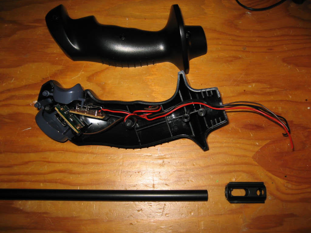
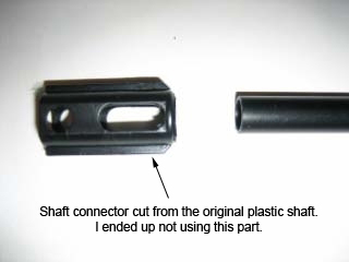
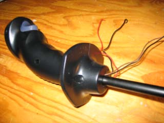
| I started by following Retropolis' instructions to open and disassemble the Raider Pro. All I wanted was the handle and the plastic
piece which connects the handle to the shaft. This required cutting the plastic shaft that comes with the Raider Pro. I used an
old dental lathe which is nothing more than a big motor mounted horizontally with a 1/4 inch drill chuck. For cutting
plastic, I used a thin fiberglass cutting wheel spinning at low speed. If I didn't have the lathe, I would have used a
Dremel tool for this cut. For cutting the aluminum shaft, I used a plumbers pipe cutter, but a hacksaw would also work.
|
|
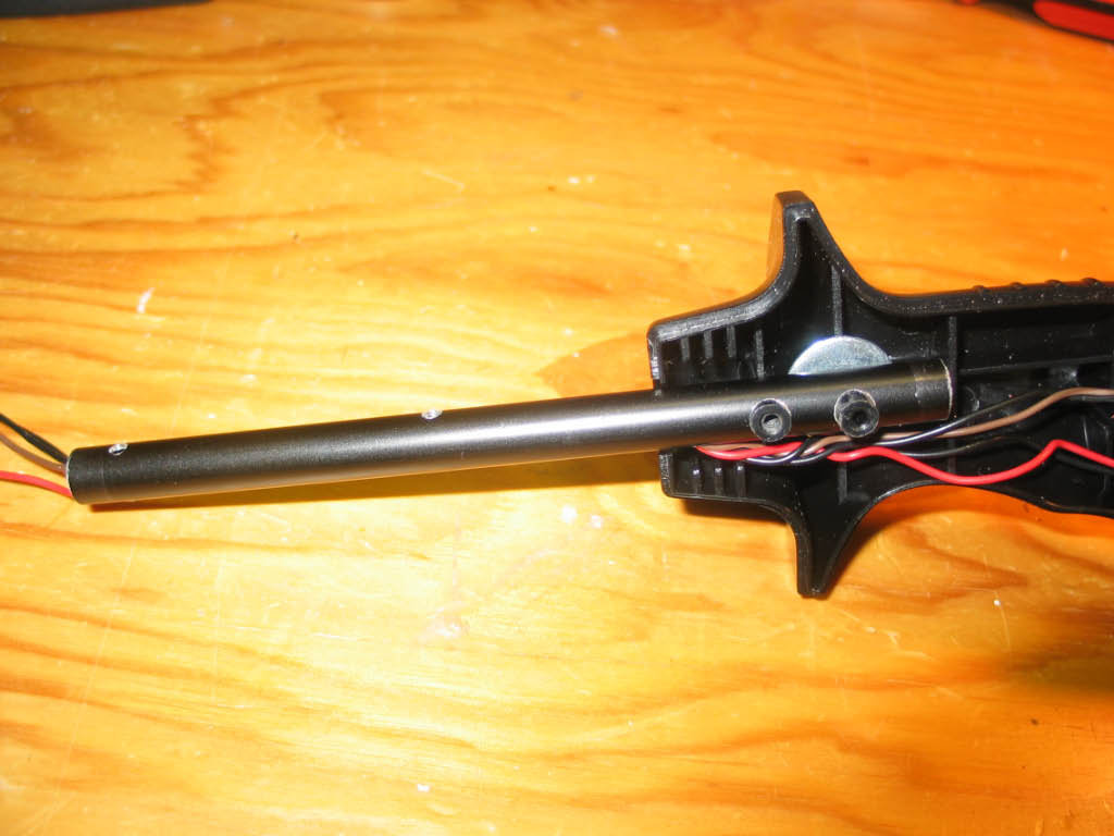
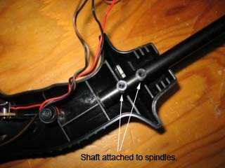
| One side of the joystick handle has two plastic spindles. The shaft connector slips over the spindles and is sandwiched between the
two halves of the handle. The 3/8 inch shaft slips into the bottom of the shaft connector about 1/2 inch before it butts up against the
first plastic spindle. Here's where I deviated from Retropolis. I decided that a 1/2 inch connection between the shaft connector
and the new aluminum shaft would not hold up to the stress of game play (even using a strong glue). Instead, I drilled
two holes into the shaft so that they would slip over the plastic spindles and the shaft connector would not be required at all.
All holes in the aluminum shaft were drilled using a drill press. |

|
| Since the shaft was slightly thinner than the original shaft connector, I added a washer over one spindle to keep
the shaft from sliding left or right.
At this point I was able to temporarily assemble the two halves of the joystick handle and the new aluminum shaft. The shaft was not
yet cut to the correct length.
|
|
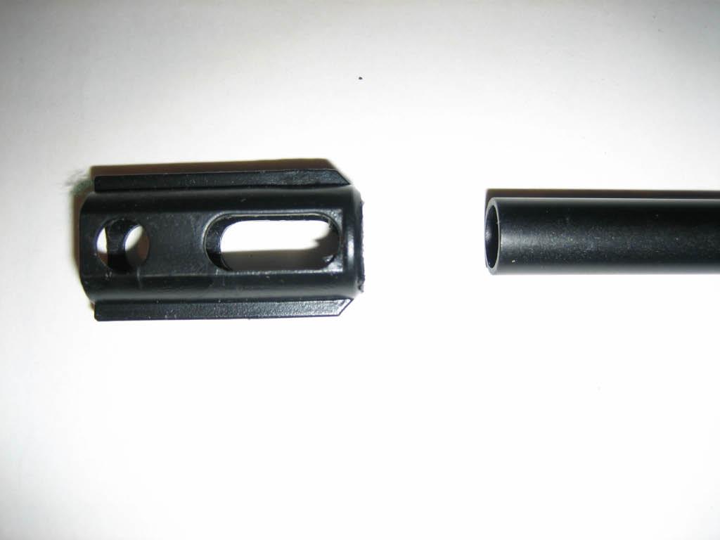
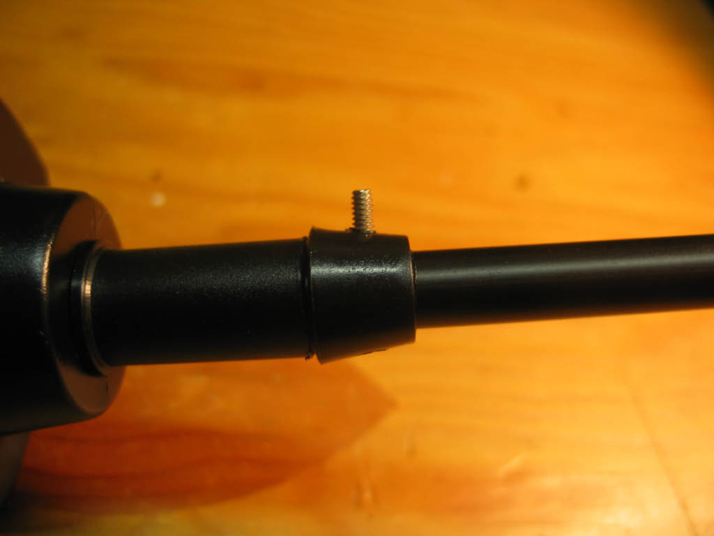
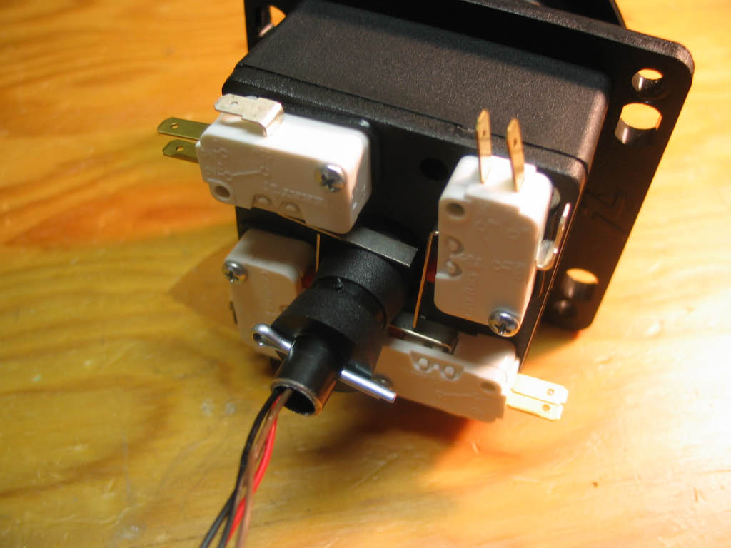
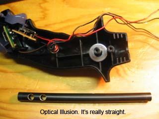
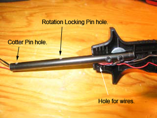
| I still needed to drill three more holes into the shaft; one to route the wires into the shaft below the connecting rods,
one for the rotation locking pin, and one for a cotter pin to secure the shaft to the base of the
Happ Super. The first hole for the wires was easy; it's 1/8 inch wide and drilled just below and 90 degrees to the two spindle holes.
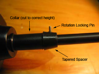
The next hole was for the rotation locking pin. I used a design very similar to 1Ups. Using the collar and tapered spacer from the
Happ Super, I placed the new joystick into the base of the Super just as the original stick would be assembled. Since my control panel
will be 3/4 inch thick, I marked and then cut the collar to the correct height to allow the new stick enough clearance
above the top of the panel. Then I reassembled the collar and tapered spacer and marked the spacer and shaft for the rotation locking pin.
For the pin, I used a small 3/4 inch bolt. I drilled a hole through both sides of the shaft big enough for the bolt. I also drilled
a hole through both sides of the tapered spacer, but on one side I enlarged the hole big enough to accept the head
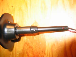
of the bolt. For the last hole, I inserted the new shaft with collar and tapered spacer into the joystick base and added
the micro-switch spacer to the bottom. Then I marked the shaft below the micro-switch spacer. I removed all the parts and drilled
a hole through both sides just below my mark for the cotter pin. This hole would be in the same place as the C-clip used to
secure the original Happ joystick shaft. And finally, I cut the shaft to length, 1/2 inch beyond the cotter pin hole.
|
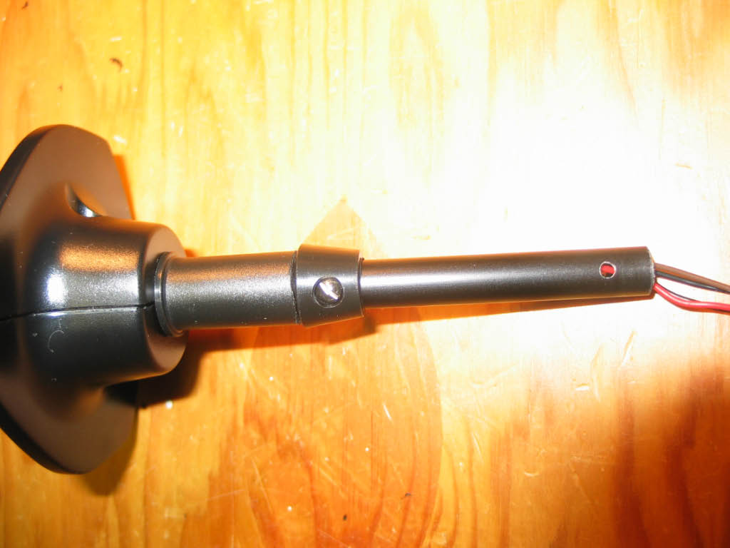
| This picture shows the wires routed through the shaft. You can also see the small holes for the rotation
locking pin and the cotter pin. |
|
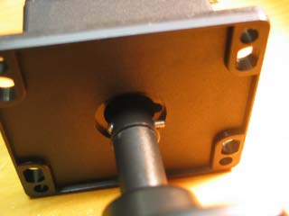
| These pictures show the collar, tapered spacer, and rotation locking pin.
|
|
| Here's a picture of the cotter pin holding it all together!.
|

|
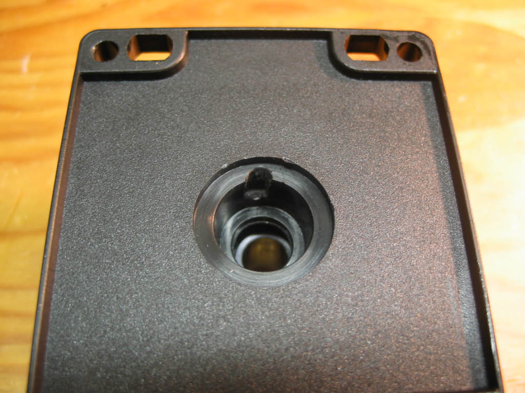
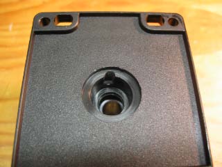
| The final step was to add a notch to the base of the joystick for the rotation locking pin.
Using the drill press, I drilled a small guide hole, then switched to a bigger bit for the notch.
|
|
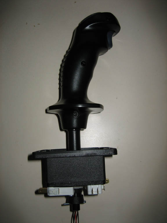
| I'm happy with the results but I still have to wire it up and see how well it works.
|
|
| Update... I purchased a NOS (New Old Stock) Heavy Duty 8-Way Trigger + Two Button
Joystick on eBay for a steal; $40! I enjoyed building my own trigger joystick, but needless to say the Heavy
Duty Arcade version is built like a tank and feels great. So my home-brew stick has been retired.
|

|